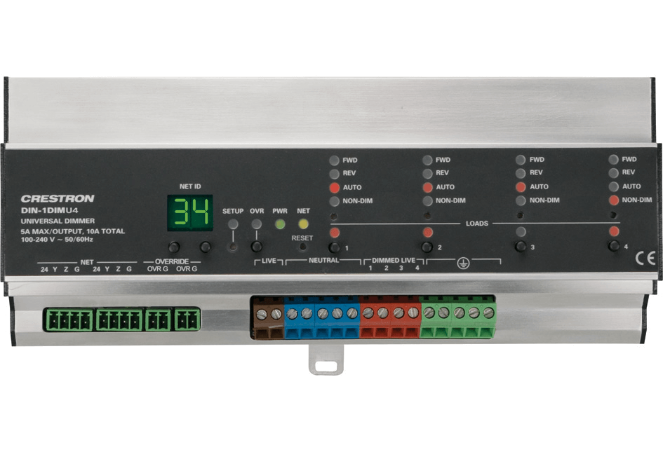
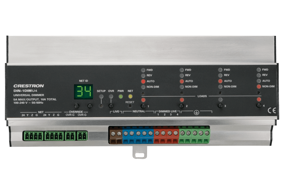
DIN-1DIMU4
The DIN-1DIMU4 is a 4-channel universal lighting control module designed to support dimming of both forward and reverse phase type loads. A single model supports both 120 and 220-240 Volt electronic and magnetic low-voltage, incandescent, neon/cold cathode, 2-wire dimmable fluorescent, and non-dimmable lighting loads up to 5 Amps per channel, 10 Amps total.
| Load Ratings | ||
| Dimmer Channels | 4 | |
| Maximum Per Channel | 5 Amps @ 120 to 240 Volts AC, 50/60 Hz; 600 Watts @ 120 Volts AC; 1150 Watts @ 230 Volts AC; 1200 Watts @ 240 Volts AC | |
| Module Total | 10 Amps @ 120 to 240 Volts AC, 50/60 Hz; 1200 Watts @ 120 Volts AC; 2300 Watts @ 230 Volts AC; 2400 Watts @ 240 Volts AC | |
| Load Types | Forward Phase (leading edge) or Reverse Phase (trailing edge) Electronic Low Voltage, Incandescent, Neon/Cold Cathode, Magnetic Low Voltage, Dimmable 2 Wire Fluorescent, & Non-Dim Lighting | |
| Minimum Load | 15 Watts/channel for Incandescent loads; 50 Watts/channel for Magnetic Low Voltage loads with Halogen or LED Lamps; 50 Watts for AC Dimmable LED loads operated in Auto/Forward-Phase Mode; 15 Watts for AC Dimmable LED loads operated in Reverse-Phase Mode | |
| Input Voltage | ||
| Line Power | 120 to 240 Volts AC, 50/60 Hz | |
| Connections | ||
| NET | (2) 4-pin 3.5mm detachable terminal blocks, paralleled; Cresnet® slave port | |
| OVERRIDE | (2) 2-pin 3.5mm detachable terminal blocks, paralleled; Sensing input for external low-voltage contact closure; Activates override mode when a closure is present; Minimum Closure Rating: 10mA (per module) at 24 Volts | |
| LIVE | (2) Captive screw terminals,[1] brown; Line power input | |
| NEUTRAL | (5) Captive screw terminals,[1] blue | |
| DIMMED LIVE 1 – 4 | (4) Captive screw terminals,[1] red; Dimmer channel outputs 1 - 4 | |
| Ground | (5) Captive screw terminals,[1] green | |
| Controls & Indicators | ||
| NET ID | (2) 7-Segment green LED digits and (2) miniature pushbuttons for setting Cresnet ID; digits also display output levels and protection/error codes | |
| SETUP | (1) Red LED and (1) recessed miniature pushbutton for enabling setup mode and touch-settable ID | |
| OVR | (1) Red LED and (1) miniature pushbutton for enabling override mode and saving override presets | |
| PWR | (1) Green LED, normally indicates AC line power is connected to either LIVE terminal, blinks when only powered by Cresnet | |
| NET | (1) Yellow LED, indicates communication with the control processor | |
| RESET | (1) Recessed miniature pushbutton, resets internal processor | |
| FWD 1 – 4 | (4) Red LEDs, illuminate when a corresponding channel is operating in forward-phase mode | |
| REV 1 – 4 | (4) Red LEDs, illuminate when a corresponding channel is operating in reverse-phase mode | |
| AUTO 1 – 4 | (4) Red LEDs, illuminate when a corresponding channel is set to auto-detect the load type | |
| NON-DIM 1 – 4 | (4) Red LEDs, illuminate when a corresponding channel is operating in non-dim mode | |
| Channel Mode Select 1 – 4 | (4) Recessed miniature pushbuttons, used to select each channel’s operating mode | |
| LOADS 1 – 4 | (4) Red LEDs and (4) miniature pushbuttons for status indication and local control of each channel | |
| Enclosure | ||
| Aluminum with polycarbonate label overlay, 35mm DIN EN 60715 rail mount, DIN 43880 form factor for enclosures with 45mm front panel cutout, occupies 12 DIN module spaces (216mm)[2] | ||
| Power Requirements | ||
| Cresnet Power Usage | 0.6 Watts (0.03 Amps @ 24 Volts DC) when line power is not available | |
| Environmental | ||
| Temperature | 32° to 104°F (0° to 40°C) | |
| Humidity | 10% to 90% RH (non-condensing) | |
| Heat Dissipation | 60 BTU/hr @240 Volts with 2 channels at 5 Amps; 50 BTU/hr @ 120 Volts with 2 channels at 5 Amps | |
| Dimensions | ||
| Height | 3.71 in (95 mm) | |
| Width | 8.49 in (216 mm) | |
| Depth | 2.35 in (60 mm) | |
| Weight | ||
| 2.1 lbs. (0.96 kg) | ||
| Standards & Certifications | ||
| CEC Title 24 2013 Compliant | ||